Digital Control Power Supply

RD6018 RD6018W 60V 18A USB WiFi DC DC adjustable Step Down voltage bench Power Supply Buck converter & 800W1000W AC DC PSU, Wholesale RD6018 RD6018W USB WiFi DC DC adjustable Step Down voltage bench Power Supply

RD6018 RD6018W 60V 18A USB WiFi DC DC adjustable Step Down voltage bench Power Supply Buck converter & 800W1000W AC DC PSU is a one of our Digital Control Power Supply Tools, you can buy RD6018 RD6018W 60V 18A USB WiFi DC DC adjustable Step Down voltage bench Power Supply Buck converter & 800W1000W AC DC PSU from foxwellpro.com.

Wholesale Top quality VAS6154, GM Tech2, VCM II For Ford, Handy Baby II Car Key Chip Copier, CDP DS150

images of RD6018 RD6018W 60V 18A USB WiFi DC DC adjustable Step Down voltage bench Power Supply Buck converter & 800W1000W AC DC PSU
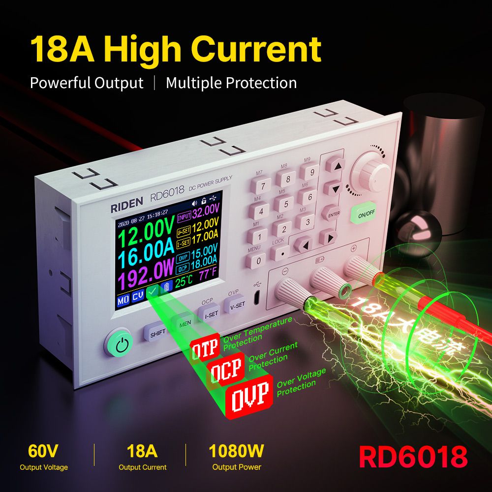
RD6018 RD6018W 60V 18A USB WiFi DC DC adjustable Step Down voltage bench Power Supply Buck converter & 800W1000W AC DC PSURD6018 RD6018W 60V 18A USB WiFi DC DC adjustable Step Down voltage bench Power Supply Buck converter & 800W1000W AC DC PSURD6018 RD6018W 60V 18A USB WiFi DC DC adjustable Step Down voltage bench Power Supply Buck converter & 800W1000W AC DC PSURD6018 RD6018W 60V 18A USB WiFi DC DC adjustable Step Down voltage bench Power Supply Buck converter & 800W1000W AC DC PSURD6018 RD6018W 60V 18A USB WiFi DC DC adjustable Step Down voltage bench Power Supply Buck converter & 800W1000W AC DC PSURD6018 RD6018W 60V 18A USB WiFi DC DC adjustable Step Down voltage bench Power Supply Buck converter & 800W1000W AC DC PSU
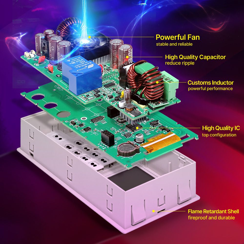
RD6018 RD6018W 60V 18A USB WiFi DC DC adjustable Step Do

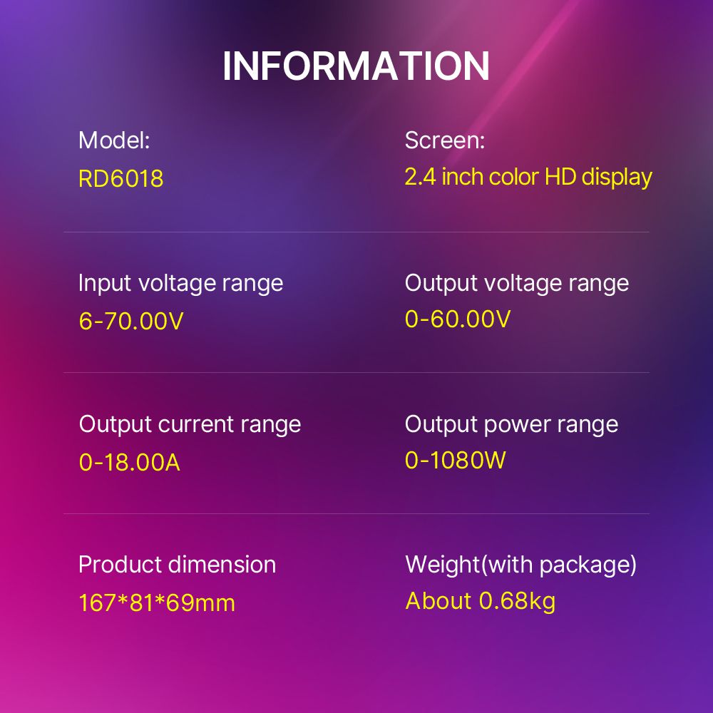
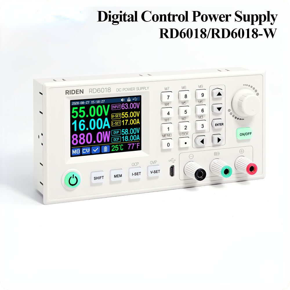
Model: RD6018/RD6018-W

Input voltage range: 6-70.00V

Output voltage range: 0-60.00V

Output current range: 0-18.00A

Output power range: 0-1080W

Input voltage measurement resolution: 0.01V

Output voltagesetting measurement resolution: 0.01V

Output current setting measurement resolution: 0.01A

Battery voltage measurement resolution: 0.01V

Input voltage measurement accuracy: ±(1%+5 digits)

Output voltage accuracybetween setting and measurement: ±(0.3%+3 digits)

Output currentaccuracybetween setting and measurement:±(0.5%+5 digits)

Battery voltage measurement accuracy: ±(0.5%+3 digits)

Automatic cut off current valuewhen charging:100mA

Output ripple typical:250mV VPP@6A

Working temperature range: -10℃~40℃

External sensor Temperature detection range:-10℃~100℃/0℉~200℉

External sensor Temperature detection accuracy:±3℃/±6℉

Constant voltage moderesponse time: 2ms(0.1A-5A Load)

Constant voltage mode load regulation: ±(0.1%+2 digits)

Constant current mode load regulation: ±(0.1%+3 digits)

Capacity measurement range: 0-9999.99Ah

Energy measurement range: 0-9999.99Wh

Capacity and energy statistical error: ±2%

Buck working mode: Voltage drop >1V and >10%

Over temperature protection: System temperature>80℃

Screen brightness setting: 0-5(6 level in total)

Screen: 2.4inch color HD display

Weight(with package):About0.68kg

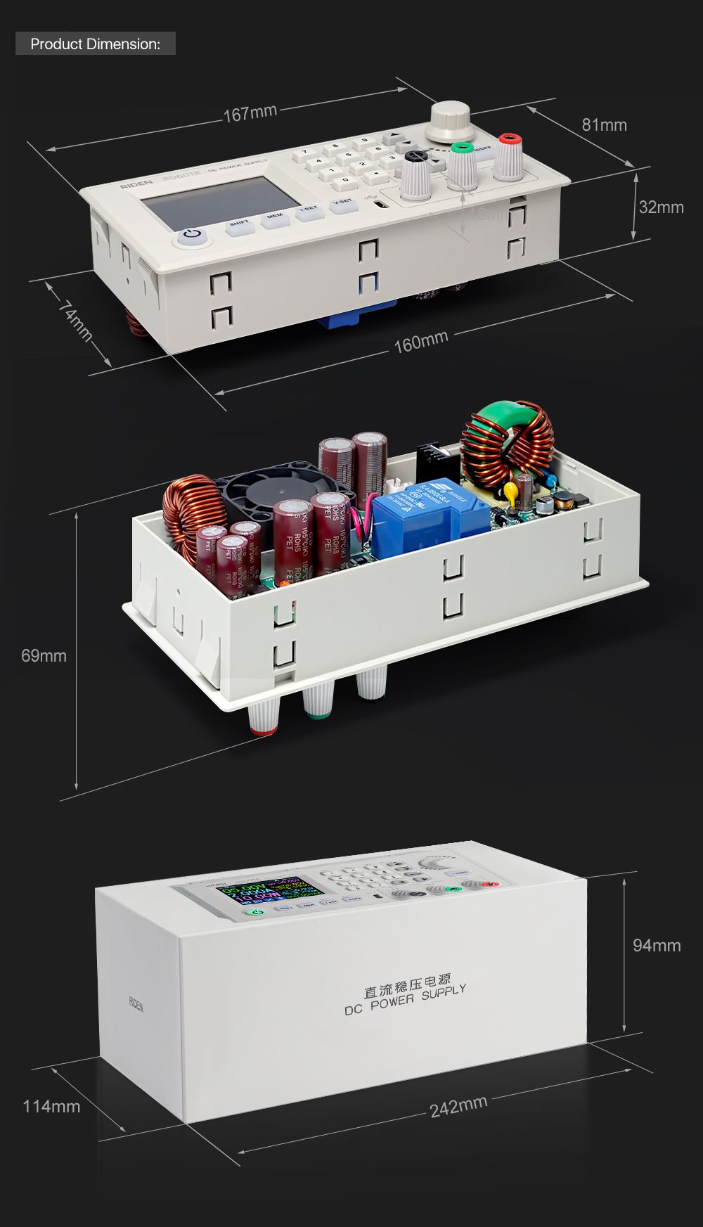
Product dimension: 167*81*69mm

Cooling fan start condition:Output current>8AorSystem temperature>45℃

Cooling fan shut down condition:Output current<7.9Aand System temperature<45℃

RD6018 RD6018W 60V 18A USB WiFi DC DC adjustable Step Do

RD6018 RD6018W 60V 18A USB WiFi DC DC adjustable Step Do

RD6018 RD6018W 60V 18A USB WiFi DC DC adjustable Step DoRD6018 RD6018W 60V 18A USB WiFi DC DC adjustable Step DoRD6018 RD6018W 60V 18A USB WiFi DC DC adjustable Step DoRD6018 RD6018W 60V 18A USB WiFi DC DC adjustable Step DoRD6018 RD6018W 60V 18A USB WiFi DC DC adjustable Step Do
RD6018 RD6018W 60V 18A USB WiFi DC DC adjustable Step DoRD6018 RD6018W 60V 18A USB WiFi DC DC adjustable Step DoRD6018 RD6018W 60V 18A USB WiFi DC DC adjustable Step DoRD6018 RD6018W 60V 18A USB WiFi DC DC adjustable Step DoRD6018 RD6018W 60V 18A USB WiFi DC DC adjustable Step DoRD6018 RD6018W 60V 18A USB WiFi DC DC adjustable Step Do

1,Instruction:

RD6018(W) operation instructon, PC software instruction , APP instruction ,APP and PC software download link:

A: Main download llink :https://drive.google.com/drive/folders/1V0l6P1sIJilN1yBOsTO9YGLVdkuO0cX9?usp=sharing

B: Mediafire:http://www.mediafire.com/folder/xc2v831oqj98g/RD6018

2,APP Download:

Android APP: download at file link:https://drive.google.com/drive/folders/1V0l6P1sIJilN1yBOsTO9YGLVdkuO0cX9?usp=sharing, Support android 8.0 -android 10.0;

Android APP Google Playdownload:Search "Ruideng" to download , support Android 8.0 and above phone

IOS APP download: Search "RdPower" to download , support IOS10.0-IOS13.4 System

3, Case Assembly:

RD6018 and S800 caseassemble instruction:https://drive.google.com/drive/folders/11Zb8hHO2ABnWO-Com304y0jQPFi8VTO7?usp=sharing

RD6018 RD6018W 60V 18A USB WiFi DC DC adjustable Step Do

1,Instruction video:

a.section 1.4.2.1Battery Charging Function Introduction:https://youtu.be/irTbqfqtgU0

b.section 1.4.2.2Output Voltage and Output Current Setting:https://youtu.be/S6Kan66dNsk

c.section 1.4.2.3Data Group Quick Storage and Call out:https://youtu.be/eo5saPjOGpo

d.section 1.4.2.4Keypad lock and unlock:https://youtu.be/zxpmasJyQ6Y

e.section 1.4.2.5System Setting:https://youtu.be/Q9d3rIgIrOc

f.section 1.4.2.6Main Page Style Setting:https://youtu.be/f51VDiY2VHE

g:section 1.4.2.7Storage Data Setting:https://youtu.be/i1kTeurS13I

h:section 1.4.2.8System Information:https://youtu.be/Um4NQObeeJE

i:section 2.1.2IOS APP Download, Installation and Connection:https://youtu.be/nH2HYwop0TE

j:section 2.4.2IOS APP Operation:https://youtu.be/lXSw1CM9IY8

k:section 3.1.1/3.2.3.2Android APP Download, Installation and Connection:https://youtu.be/QwyBEUCnp9c

l:section 3.2.3.3Anroid APP Operation:https://youtu.be/hqrF4keTfbE

m:section 4.1/4.3.1PC Software Download and basic operation:https://youtu.be/mjt1RMaah1Y

o:section 4.3.2Firmware Upgrade:https://youtu.be/NOoLfDw0DiY

p:section 4.3.3Calibration:https://youtu.be/c9sn1wY2mjE

q:section 4.3.4Logo Update:https://youtu.be/vuVhBsohWts

r: RD6006 wifi connection Problem and solution:https://www.youtube.com/watch?v=7sTtc1kweJM

2,PSU Notification

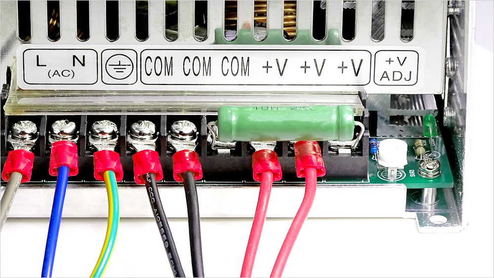
If you order the PSU, after getting the PSU, please use multimeter to check if the real output voltage is stable and fits the rated voltage, to see if it is damaged on the way, if the output is abnormal, please contact us, do not connect it to RD power supply to avoid more loss

800W PSU can let RD6018 output 60V or output 18A, but it cannot let RD6018 full output 60V 18A at the same time, because it is lower than the max output power of RD6018(1080W)

1000W PSU is 68V 17A output at 220V AC input, it can let RD6018 full output, but it is 68V 14.7A (about 1000W) at 110V AC input, so it cannot let RD6018 full output, please set the power limit to 950W in RD6018 setting. It can be placed in S800 case.
RD6018 RD6018W 60V 18A USB WiFi DC DC adjustable Step Do

RD6018 RD6018W 60V 18A USB WiFi DC DC adjustable Step Do

3,Assembly Notification

You can only connect the cables with a foundation in electronic and electrical engineering and it must be reliably grounded!

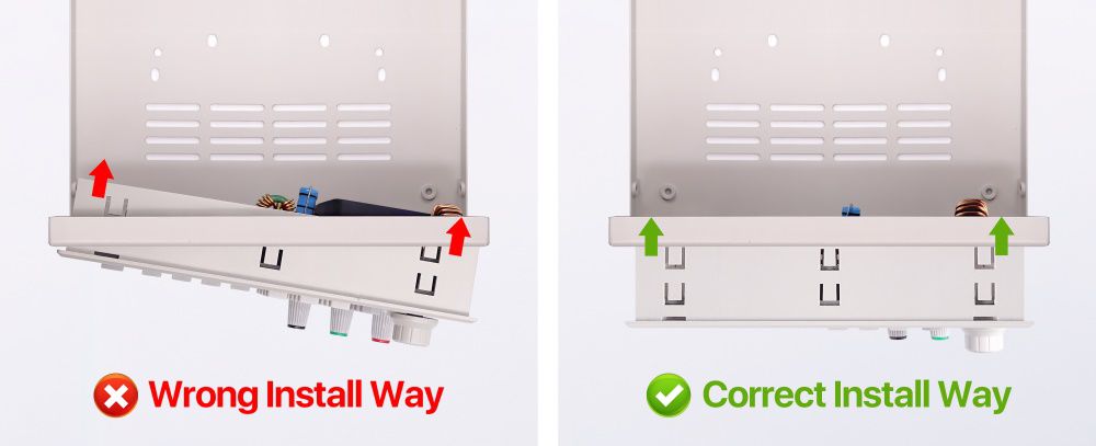
4,Correct Installation

RD6018 RD6018W 60V 18A USB WiFi DC DC adjustable Step Do

5, Actual Test Video

https://youtu.be/09XbO148WYg

1. Q: What is the differences between RD6018 and RD6018-W?

A: RD6018-W has WIFI board , RD6018 doesn't have. RD6018-W can use WIFI board to connect APP, also use USB micro cable to connect PC software . RD6018 doesn't have WIFI board, only support PC software by connecting with USB micro cable, no support APP.

2. Q: What can I get in this link?

A: the option title and pictures shows what you can get, please check and make the order.

3. Q: What does S800 case contains?

A: For S800 case, it is just case, not containing any power supply, it contains the internal cables and screws, it is suitable for RD6012/RD6018/RD6024 and AC-DC 800W/1000W switching power supply, you can buy them separately to assemble then together.

RD6018 RD6018W 60V 18A USB WiFi DC DC adjustable Step Do

4. Q: Why the product I get is a bit different with the picture?

A: We keep updating the product hardware and software to make the device better, so the internal material details may be different, but it does not affect you to use the functions.

5. Q: why does the instruction not come with the product?

A: Because the products keep updating, we will add some function with the firmware and hardware update, so you can download the instruction online.

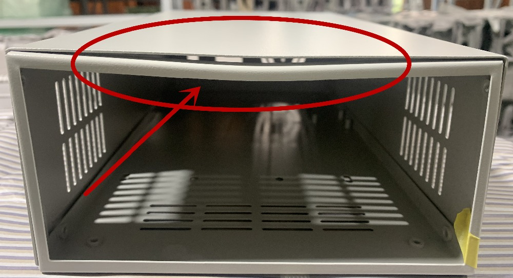
6. Q: the case I receive is a bit deformed?

A: For the case, during the shipping,maybe the case side will be a little deformed (just like picture ), you can use your hand to adjust, that's OK, if you mind this , please stop buying.

RD6018 RD6018W 60V 18A USB WiFi DC DC adjustable Step Do

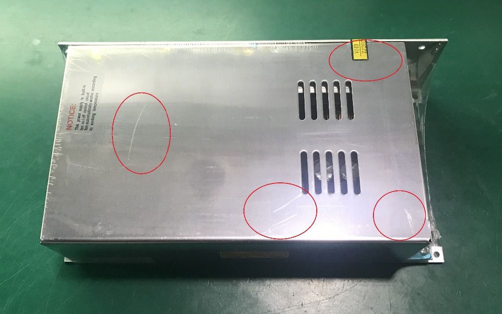
7. Q: the PSU I receive have some scratches?

A: There may be scratches on the surface but it doesn't affect the product performance, please do not be over picky, and if you do mind this, please do not buy this product

RD6018 RD6018W 60V 18A USB WiFi DC DC adjustable Step Do

8. Q: the warranty label is broken, do I still get the warranty?

A: Due to express delivery, some power supply warranty labels may be damaged, which does not affect product warranty!

9.Q: How do I choose the PSU?

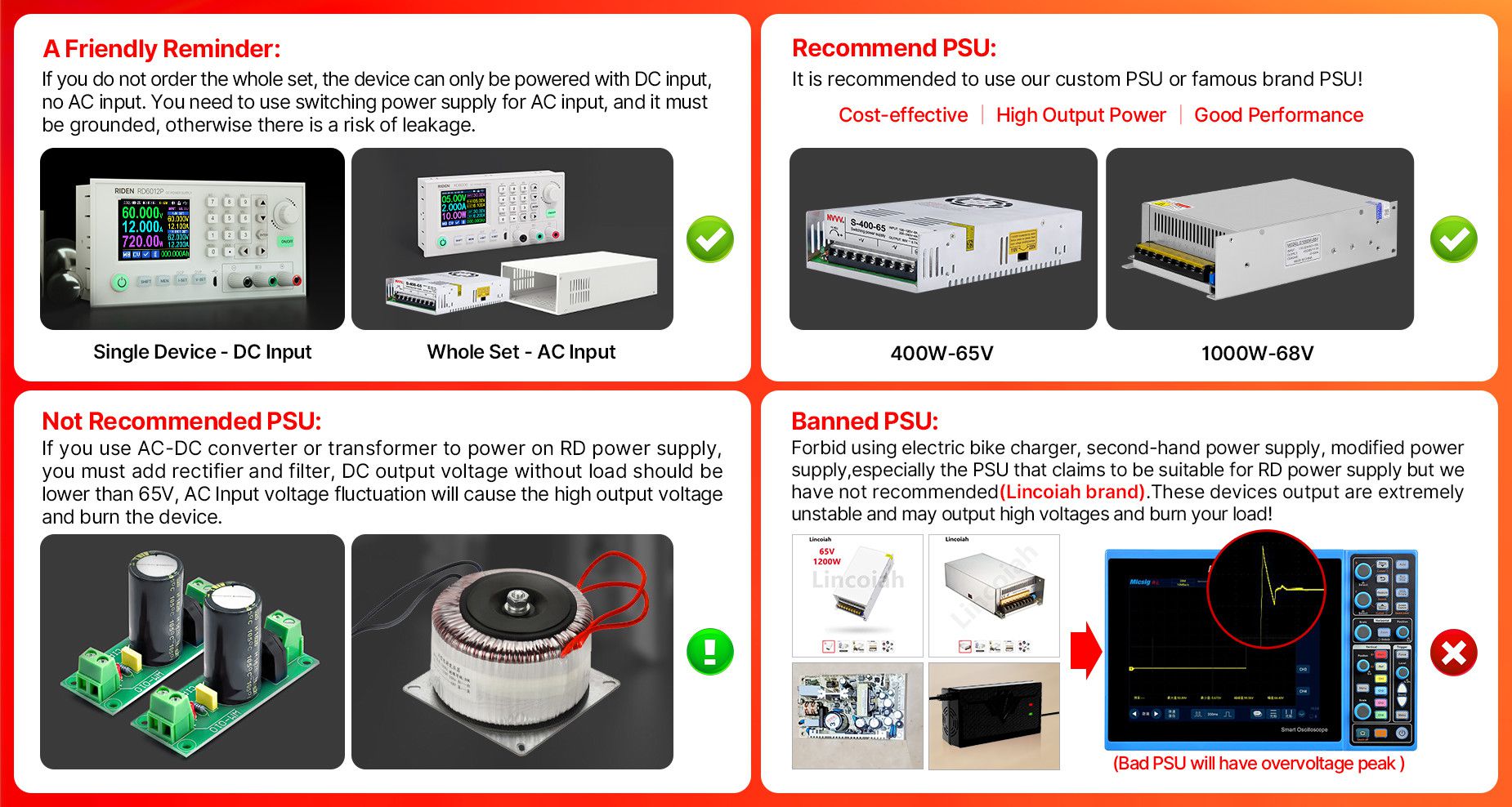
A:Friendly reminder, If you do not order the whole set, the device can only be powered with DC input, no AC input. You need to use switching power supply for AC input, and it must be grounded, otherwise there is a risk of leakage.

AA: Recommend PSU

It is recommended to use our custom PSU or famous brand PSU!

BB: Not recommended PSU

If you use AC-DC converter or transformer to power on RD power supply, you must add rectifier and filter, DC output voltage without load should be lower than 65V,power grid voltage fluctuation will cause the high output voltage and burn the device!

CC. Banned PSU

Forbid using electric bike charger, second-hand power supply, modified power supply, especially the PSU that claims to be suitable for RD power supply but we have not recommended ......These devices output are extremely unstable and may output high voltages and burn your load!

(bad PSU will have peak over-voltage)

RD6018 RD6018W 60V 18A USB WiFi DC DC adjustable Step Do

11.Q: Can I use it to power on inductive load?

A: If you connect inductive load (such as motor), the max working current is 1/3 of range. don't exceed it.

12. Q:why there is a fuse in the box? Should I install it?

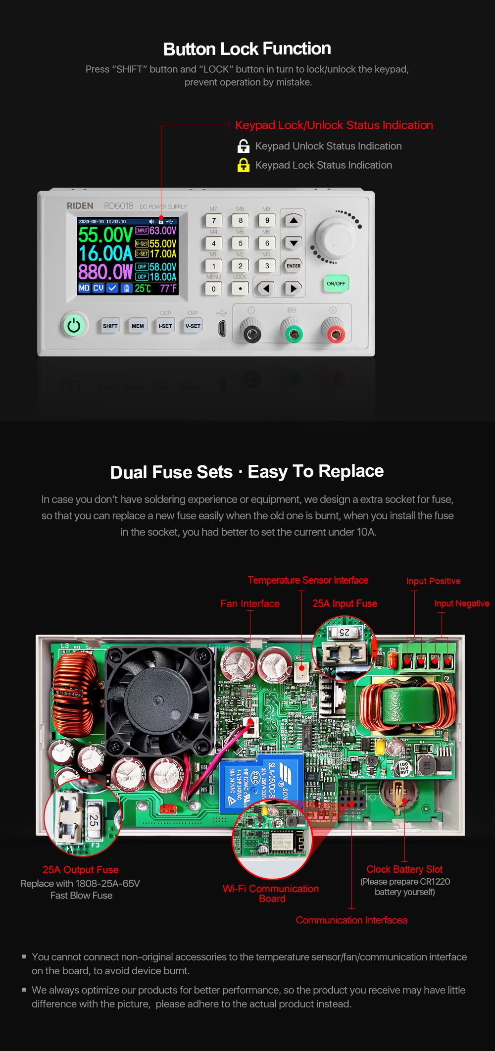
A:It is a BACKUP fuse in the, if you burn the fuse with wrong operation, you can insert the fuse in the socket next to the burned one for temporary use and it supports only 10A, so it is better to remove the damaged fuse and solder the good fuse on the same position for full output.

13. Q: can I remove the case of the PSU for better heat dissipation?

A: when install our PSU into the case, please follow our instruction to assemble, do not remove the shell of the PSU to use. After removing the shell of the switching power supply, the structural change of the heat dissipation system will lead to insufficient heat dissipation,and some components will be overheated and damaged, in this case we don't offer after sell service

14. Q:Does the 800W65V PSU has high-frequency noise?

A:there may be high-frequency noise when the 800W65V switch power supply is powered on and there is no load, which can be improved by adding a load resistoras shown in the figure! But for some people, they can still hear the noise, if you mind the noise, please do not buy this power supply

RD6018 RD6018W 60V 18A USB WiFi DC DC adjustable Step Do

SOFTWARE QUESTIONS:

1. Q: The APP crashes on my phone, what the problem is?

A: For APP and PC software, because there may be incompatibilities problems, please download first before buying , if you can download and install, you can make order, or else stop buying. If you don't test the PC software and APP function before buying and find that the products works fine except the PC software or APP, we refuse to refund.For PC software, it only support win 7 and above for now. For APP, it only support android 8.0 and above.

2. Why cannot I connect the RD6018W to my phone APP via WIFI?

A: Please check if the WIFI board is inserted properly, then check if the WIFI is 2.4G Hz and if you shut down the client isolation/ AP isolation and WMM function, and check if you turn on the location service and storage service when you install the APP. If there is still problem, contact us.

3.Why cannot I connect the RD6018W to PC via WIFI while I can connect to the Phone?

A:WiFi connection is a test function, due to poor compatibility of some computers, if you cannot connect PC software via WiFi, please ignore this function. Forthis function, we do not provide any guarantee and technical support, and we will decide whether to keep this function based on customer feedback.

RD6018 RD6018W 60V 18A USB WiFi DC DC adjustable Step Do

Model

RD6006

RD6012

RD6018

RD6006P

RD6012P

RD6024

Input voltage range

6-70.00V

7-70.00V

7-70.00V

6-70.00V

Output voltage range

0-60.00V

0-60.000V

0-60.000V

0-60.00V

Output current range

0-6.000A

0-12.00A

0-18.00A

0-6.0000A

0-6.0000A/

0-12.000A

0-24.00A

Output power range

0-360W

0-720W

0-1080W

0-360W

0-720W

0-1440W

Output voltage setting measurement resolution

0.01V

0.001V

0.01V

Output current setting measurement resolution

0.001A

0.01A

0.0001A

0.001A/

0.0001A

0.01A

Output voltage accuracy between setting and measurement

±(0.3%+3 digits)

±(0.5‰+4 digits)

±(0.3%+3 digits)

Output current accuracy between setting and measurement

±(0.5%+5 digits)

±(1‰+6 digits)

±(0.5%+5 digits)

Automatic cut off current value when charging

10mA

100mA

Set by yourself

Set by yourself

Set by yourself(higher than 100mA)

Output ripple typical

100mV VPP

250mV VPP@6A

20mV VPP

100mV@12A,150mV@24A VPP

Buck working mode

Voltage drop >1V and >10%

(input voltage÷1.1)-2

(input voltage÷1.1)-1

Weight(with package)

About 0.58kg

About 0.61kg

About 0.68kg

About 0.62kg

About 0.66kg

About 0.72kg

Product dimension

167*81*65mm

167*81*69mm

167*81*65mm

167*81*69mm

①:Ripple measurement method: noise and ripple are measured at X1 range, AC coupling,

20MHz of bandwidth on your oscilloscope with a 0.1uF parallel capacitor at the output terminals

②for example: input voltage is 24V,the max output voltage is 19.8V.

RD6018 RD6018W 60V 18A USB WiFi DC DC adjustable Step Do
Constant Voltage and Constant CurrentDC Power Supply Instruction
Model: RD6006/RD6006W/ RD6012/RD6012WRD6018/RD6018W
Date: 2020.9.14
Dear users, thank you for purchasing the constant voltage constant current DC power supply produced by Hangzhou Ruideng Technology Co., Ltd. In order to let you know more about the full function of this product, get a better experience and avoid misuse. Please read this instruction carefully before using it. Keep it for future reference.
Note: This instruction is corresponding to firmware V1.30, the page and operation may be different under different firmware versions, please pay attention when using it. We do recommend you to download the latest firmware for better experience.
1.1Technical Parameter
check the chart above
1.2 Core Function
·Keypad + encoder potentiometer combination adjustment
·10 data groups for storage and call out
·Firmware update, support more functions later
·2.4 inch HD color display
·Dedicated terminal for battery charging
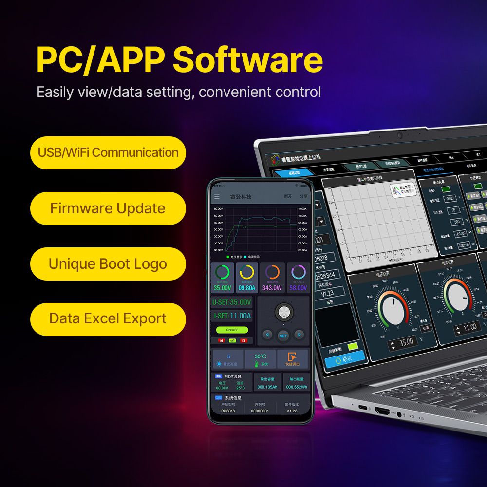
·Brand new PC software
·Support WiFi communication /USB communication
·Support Android/ IOS APP
·Support multiple display interfaces
1.3 Panel Instruction
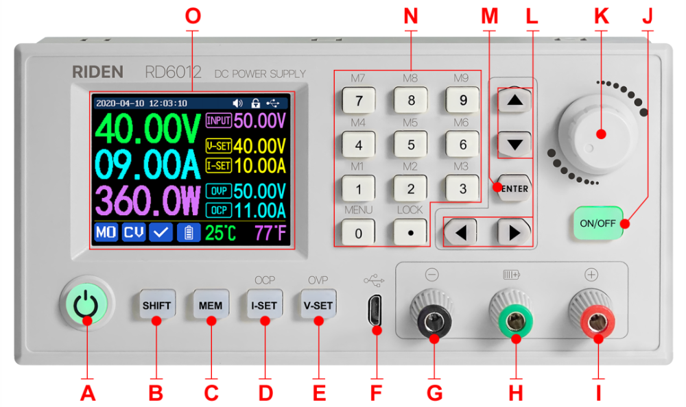
1.3.1 Front Panel
RD6018 RD6018W 60V 18A USB WiFi DC DC adjustable Step Do
A: Power button
B: SHIFT Second function button
C: Quick storage button
D: Current/Over current protection setting
E: Voltage/Over voltage protection setting
F: Micro USB port
G: Power supply output negative terminal/
Battery charging negative terminal
H: Battery charging positive terminal
(Dedicated terminal for battery charging)
I: Power supply output positive terminal
J: Output switch
K: encoder potentiometer/Cancel button
L: Direction button
M: Enter/ Confirm button
N: keypad
O: Screen
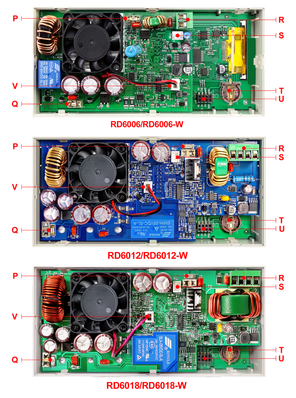
1.3.2 Back Panel
RD6018 RD6018W 60V 18A USB WiFi DC DC adjustable Step Do
P: Input fuse
Q: Output fuse
R: Power source input interface
S: External temperature sensor interface
T: CR1220 battery socket
U: Communication module interface
V: Fan interface
NOTE:
Power source input interface must be connected to 6-70V constant DC power source. The external sensor cable (as shown on right) must be connected to the external temperature sensor interface. The fan interface cannot be connected to other fans. When the system temperature is higher than 80℃, the output will be shut down and show OTP on the scrren. CR1220 is the clock battery (Please prepare by yourself), it can power on the clock function. Communication interface is a special interface, please don’t connect to other modules or cables.
RD6018 RD6018W 60V 18A USB WiFi DC DC adjustable Step Do
You can see the Wi-Fi module and RS-485 module in the picture below. If you need RS-485 for industrial batch test and it is not on sale now, if you want to use that, please contact us.
RD6018 RD6018W 60V 18A USB WiFi DC DC adjustable Step Do
1.4 Operation Instruction
After power-on, it will show boot image first, and then enters the main page. We use RD6012 as example to introduce how to use it.
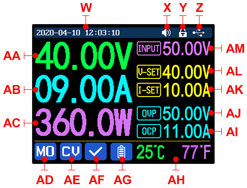
1.4.1 Main Page
RD6018 RD6018W 60V 18A USB WiFi DC DC adjustable Step Do
W: Time
AF: Protection status indication
X: Button tune
AG: Battery charging indication
Y: Button lock status
AH: Battery related information display area
Z: Communication interface
AM: Input voltage
AA: Actual output voltage value
AL: Output voltage preset value
AB: Actual output current value
AK: Output current preset value
AC: Output power
AJ: Over voltage protection value
AD: Current data group
AI: Over current protection value
AE: Constant voltage Constant current status
1.4.2Operation Introduction
In the menu operation, the icon in red or cursor is the currently selected menu, the icon in blue is not selected, pressENTERto confirm, press the encoder potentiometer to cancel or return, press the direction button to move the cursor or switch menu, rotate the encoder potentiometer to change the setting, the settings will be automatically saved when returning from the menu page. Press and hold the 0 button and power on to restore the factory settings, press and hold the 1 button and power on to restore the factory calibration value, press and hold ENTER and power on to enter the boot mode.
1.4.2.1 Battery Charging Function Introduction
Battery charging operation video:https://youtu.be/irTbqfqtgU0
After power-on, at battery related information display area, external temperature, capacity and energy will loop display. When there is output current: capacity, energy automatically accumulated, and automatically cleared after shutdown.
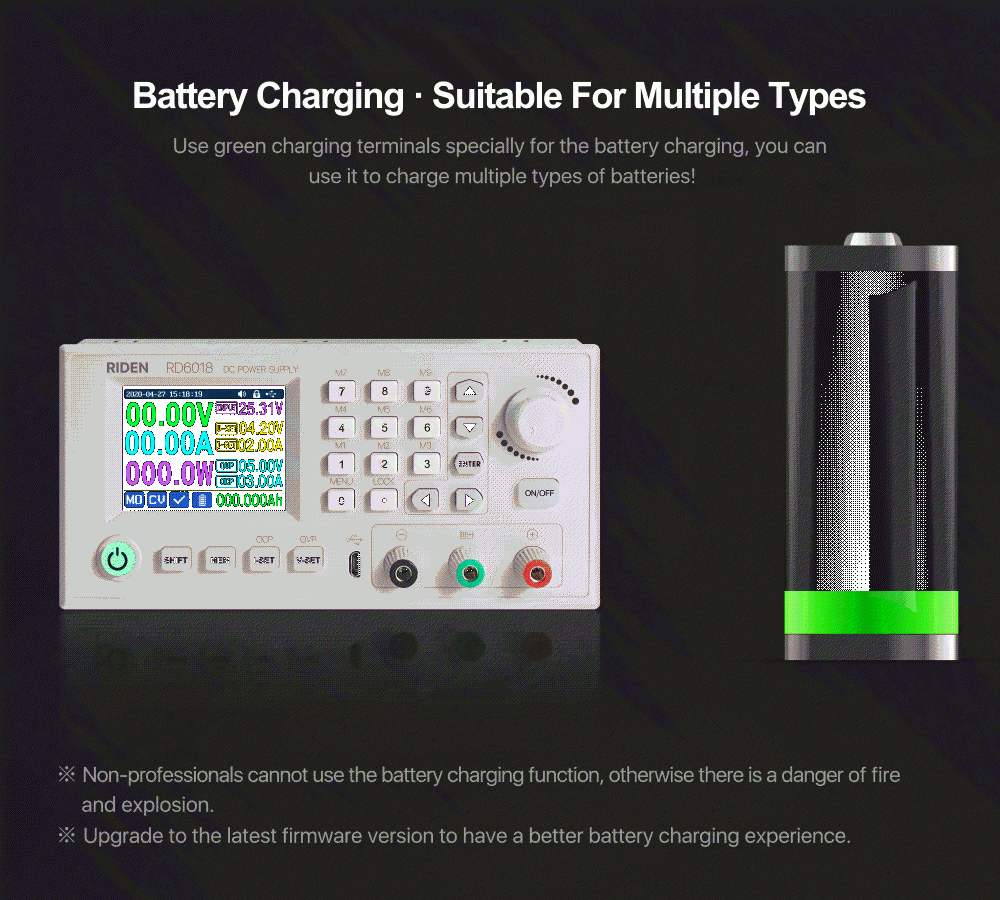
The green terminal is connected to the positive pole of the battery, and the black terminal is connected to the negative pole of the battery. After the battery is correctly connected, the battery charging indicator turns red and the battery is connected. Press ON/OFF to start charging, the battery charging indicator turns green. When the actual output current is lower than 0.1A (10mA for RD6006), the output will be shut down automatically. Battery with protection board need to be charged with red and black terminals. The charging voltage and current should be set on your own. When the charging function is not in use, you can connect the green and black terminals with a cable to prevent interference with the battery detection terminal and accidentally turn off the output.
It is strongly recommended to use the original charger to charge the battery. The charging function of this machine can only serve as a temporary replacement, not for long-term use. There is a risk of fire and explosion during the charging process. Non-professionals should not operate.
1.4.2.2Main Page Output Voltage and Output Current Setting
Output voltage and current setting operation video:https://youtu.be/S6Kan66dNsk
Press “I-SET”button to set the output current value, you can use encoder potentiometer to adjust the output value directly, press the direction button to move the cursor. Of course you can use keypad to enter the value, and press “ENTER” to confirm. If you set the wrong value, you can press encoder potentiometer to cancel.
Press “V-SET”button to set the output voltage value, the operation method is similar to output current setting.
Press“SHIFT”+ “I-SET”button /“SHIFT”+ “V-SET”button to set the over current protection/ over voltage protection value. The operation method is similar to output current setting.
M0 is the default data group when RD6006 is powered on, manually modify the settings will automatically be record to M0 after confirmation.
RD6018 RD6018W 60V 18A USB WiFi DC DC adjustable Step DoRD6018 RD6018W 60V 18A USB WiFi DC DC adjustable Step Do
1.4.2.3Data Group Quick Storage and Call out
Data group quick store and call out operation video:https://youtu.be/eo5saPjOGpo
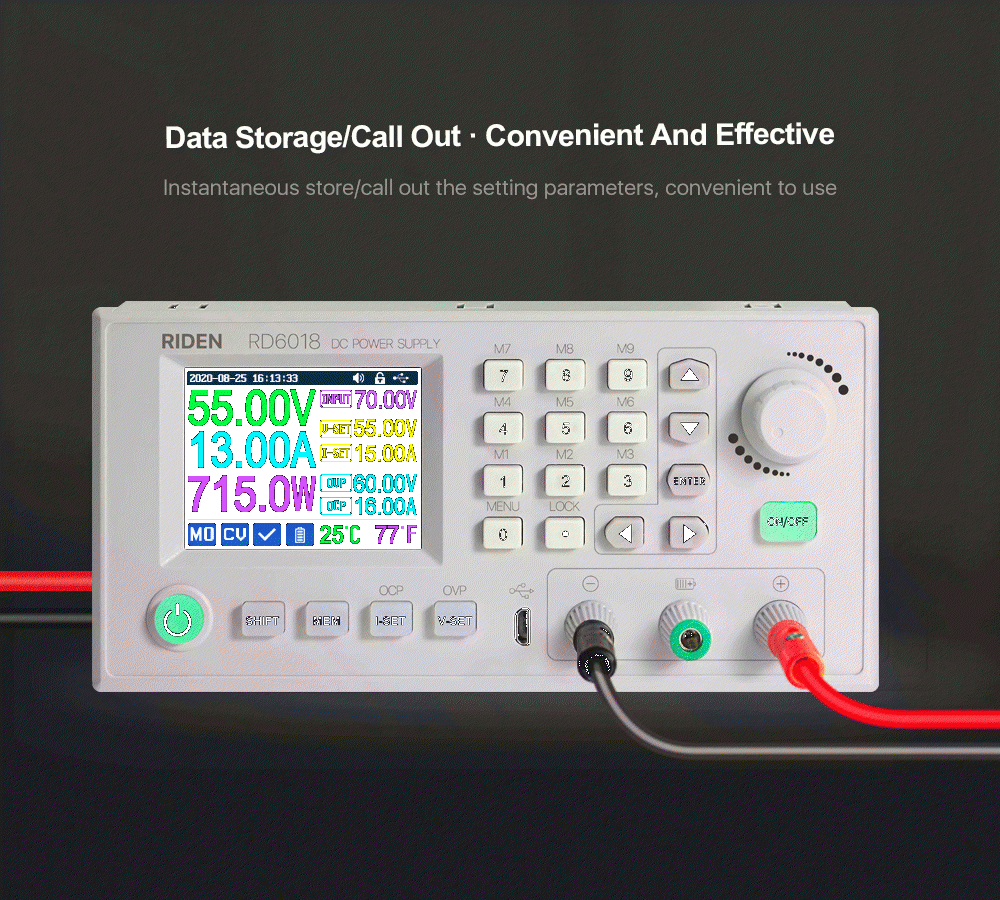
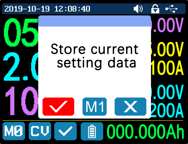
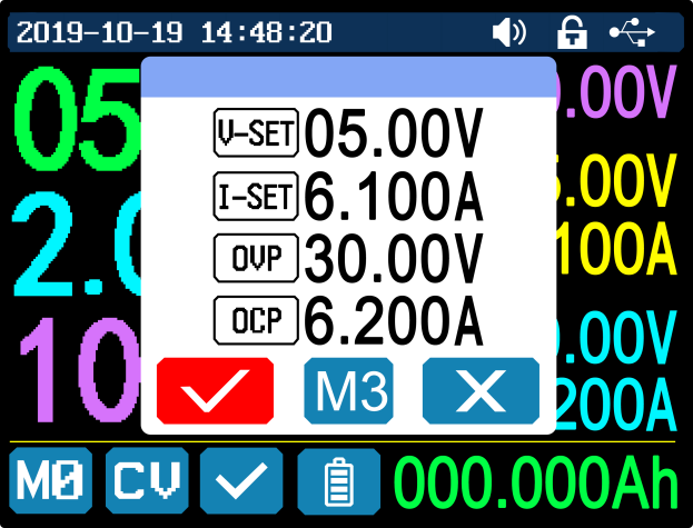
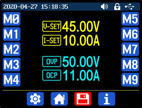
Press“MEM”+ keypad button 1-9, you can store the output voltage value, output current value, over voltage protection value, over current protection value into the corresponding data group(as shown above), then press“ENTER”to confirm, or press the encoder potentiometer to cancel.
Press“SHIFT”+ keypad button 1-9 to quick call out the saved data (as shown above). Press“ENTER”to confirm, or press the encoder potentiometer to cancel.
1.4.2.4Keypad lock and unlock
Keypad lock operation video:https://youtu.be/zxpmasJyQ6Y
Press“SHIFT”+”LOCK”to lock or unlock the keyboard. And the keypad will be automatically locked when communication starts, there will beRD6018 RD6018W 60V 18A USB WiFi DC DC adjustable Step Dodisplayed on the top (cannot unlock manually), and the keypad will be automatically unlocked when the connection disconnected manually, there will beRD6018 RD6018W 60V 18A USB WiFi DC DC adjustable Step Dodisplayed, the keypad will be automatically unlocked when the connection disconnected abnormally, and the power off button can be used when the keypad is locked.
1.4.2.5System Setting
System setting operation video:https://youtu.be/Q9d3rIgIrOc
RD6018 RD6018W 60V 18A USB WiFi DC DC adjustable Step Do
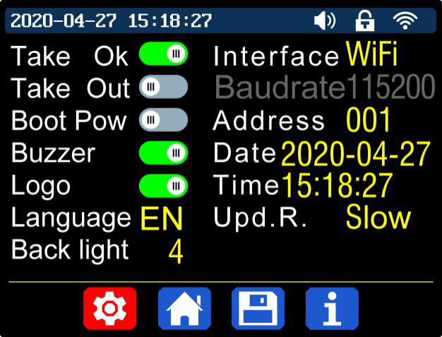
Press“SHIFT”+”MENU”to enter the system setting menu as shown below, press“ENTER”to enter the menu, press direction button to select option, the option in red is the option be chosen, rotate the encoder potentiometer to change setting.
Turn on the “TakeOK”, a confirmation window will pop up when you quick call out a data group. If you turn it off, the setting values will be modified directly when you call out a data group.
Turn on the“Takeout”, the output will be turn on automatically when you call out a data group. If you turn it off, the output will keep the previous status.
Turn on the“BootPow”,it will turn on the output automatically when start. If you turn it off, the output will keep OFF status when started.
Turn on the“Buzzer”,you will hear button tune when press the button, and there will beRD6018 RD6018W 60V 18A USB WiFi DC DC adjustable Step Doon the top. If you turn it off, there will not be button tune when press the button, and there will beRD6018 RD6018W 60V 18A USB WiFi DC DC adjustable Step Doon the top.
Turn on the“Logo”, it will display Logo first and then enter the main page when boot RD6006. If you turn it off, you will enter the main page directly.
The system language supports Simplified Chinese, English, German and France for the time being; the screen brightness can be set from level 0 to level 5; The communication interface can be set to USB, Wi-Fi or TTL,USBinterface is the Micro-USB interface on the front panel interface, you can see theRD6018 RD6018W 60V 18A USB WiFi DC DC adjustable Step Doon the top when communication starts.Wi-Fiinterface is the Wi-Fi module inserted to the communication interface, you can see theRD6018 RD6018W 60V 18A USB WiFi DC DC adjustable Step Doon the top when communication starts (connect mobile phone by Wi-Fi, WiFi function only support connection control in LAN),TTLis not available for the time being; When the interface is changed, you need to reboot RD6006 to apply the modification. The baud rate can be set to 9600/19200/38400/57600/115200 under USB mode; The Baud rate under Wi-Fi is fixed at 115200. Device address can be set from 001-255. You can set the date and time by rotating the encoder potentiometer, the setting will be saved immediately after modification. Please do not set a wrong time, it may cause that the date will not be automatically accumulated. Press the encoder potentiometer to return, and the set value will be saved automatically.Upd.R.is the refresh rate of read back voltage and current in the main page, you can set it to low, middle and high. We add output power limit function, when you set that, the current will be adjusted automatically to the value which multiply by set voltage value will not exceed the power limit, so that it can protect the input PSU, it is recommended to set the output power value at (rated power of PSU*95%). Press encoder potentiometer to return and save the settings.
RD6018 RD6018W 60V 18A USB WiFi DC DC adjustable Step DoRD6018 RD6018W 60V 18A USB WiFi DC DC adjustable Step Do
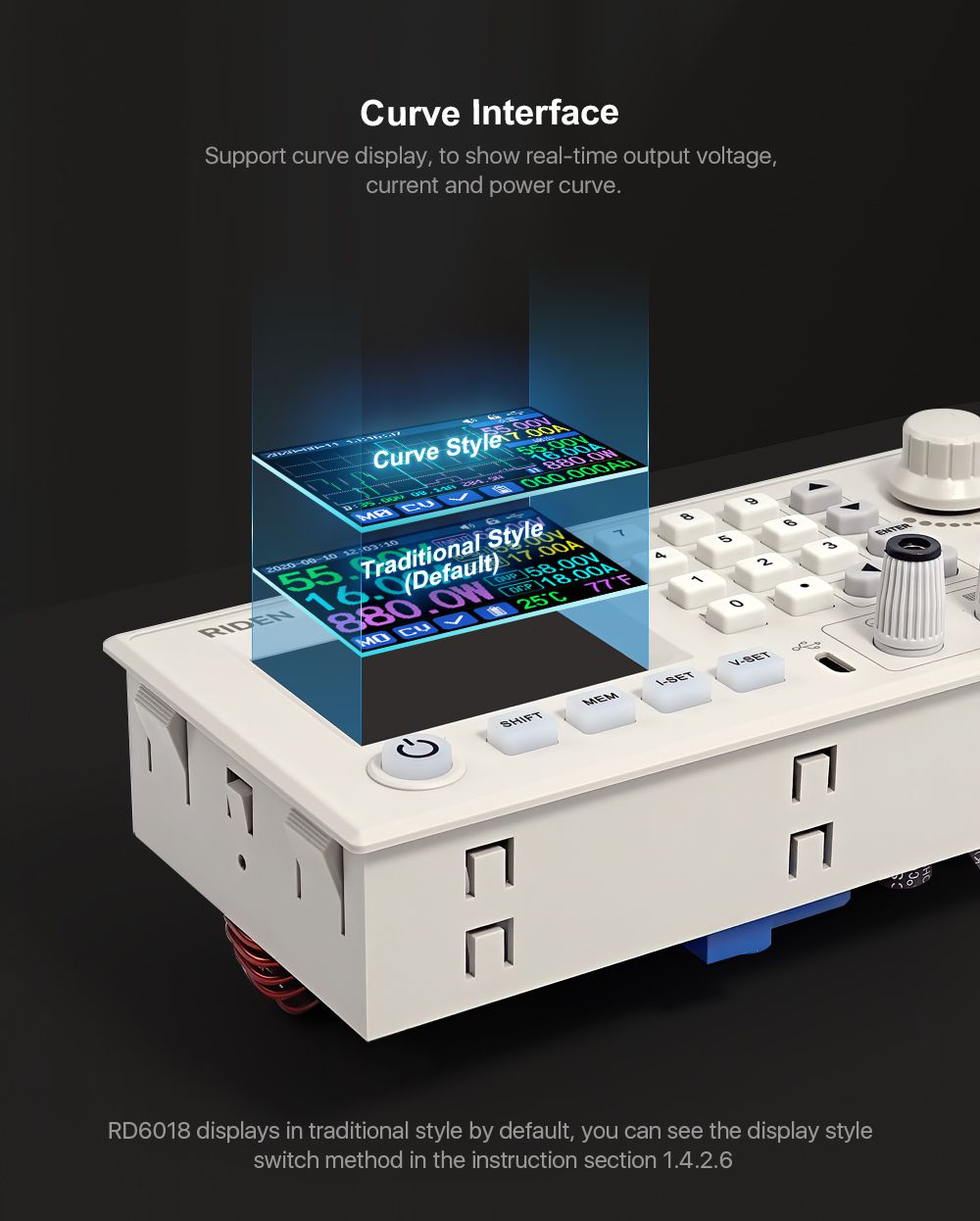
1.4.2.6 Main Page Display Style Setting
Main interface display style setting operation video:https://youtu.be/f51VDiY2VHE
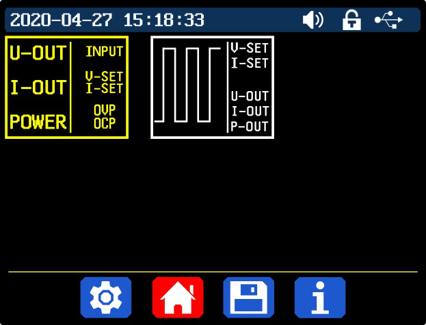
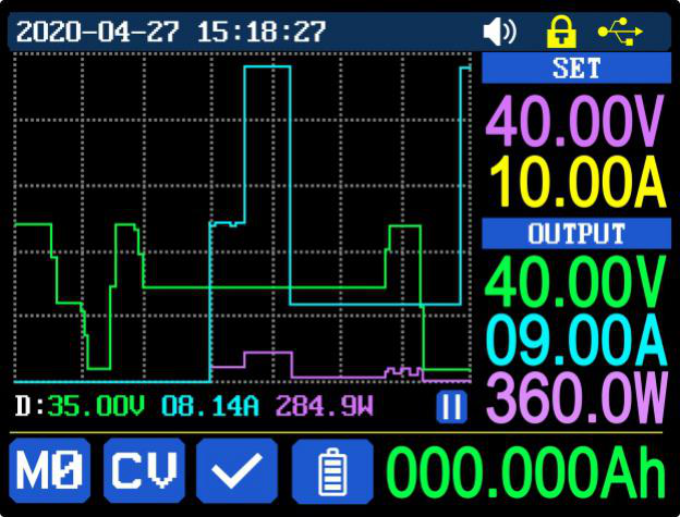
You can press SHIFT + MENU to enter the system setting menu, and then press the right button to enter the main page style setting menu as shown above. Press ENTER and then use direction button to set classic style or curve style. The pattern in red is the style being chosen. Press the encoder potentiometer to return and save the settings. The classic style is the system default style, it shows the voltage, current and power in large font. The curve style is as shown above, the color of the three curves corresponds to the output voltage, current and power. D is the scale of the ordinate, Press“ENTER”to start or pause the curve, and rotate the encoder potentiometer to scale the ordinate of the curve.
1.4.2.7Storage Data Setting
Data group setting in manual operation video:https://youtu.be/i1kTeurS13I
You can press SHIFT + MENU to enter the system setting menu, and then press the right button twice to enter the data storage setting menu as shown below, press ENTER to enter the setting menu, the icon in red is the chosen data group, press the direction button to select data group number. Press “I-SET”button to set the storage output current value, then rotate the encoder potentiometer the adjust the output value, press the direction button to move the cursor. You can also set the value with keypad, press ENTER to confirm. If you set the wrong value, you can press the encoder potentiometer to cancel. Press “V-SET”button to set the storage output voltage value, the operation method is similar to storage output current setting.
Press“SHIFT”+ “I-SET”button or“SHIFT”+ “V-SET”button to set the storage over current protection/ storage over voltage protection value. The operation method is similar to storage output current value setting. Press encoder potentiometer to return, and the data will be automatically saved.
RD6018 RD6018W 60V 18A USB WiFi DC DC adjustable Step DoRD6018 RD6018W 60V 18A USB WiFi DC DC adjustable Step Do
1.4.2.8System Information
System information operation video:https://youtu.be/Um4NQObeeJE
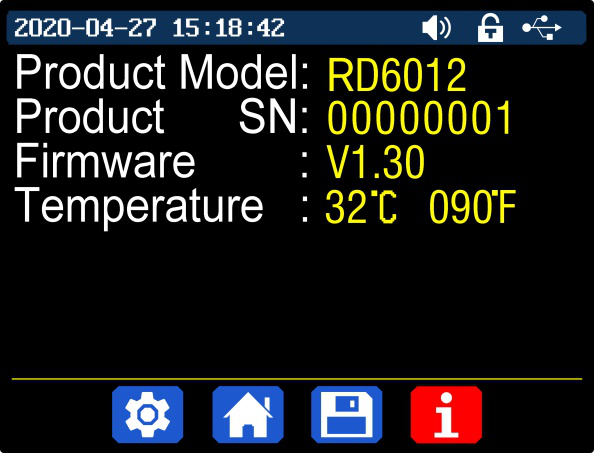
You can press SHIFT + MENU to enter the system setting menu, and then press the right button three times to enter the system information menu as shown above. You can view the SN number, firmware version and system temperature here.
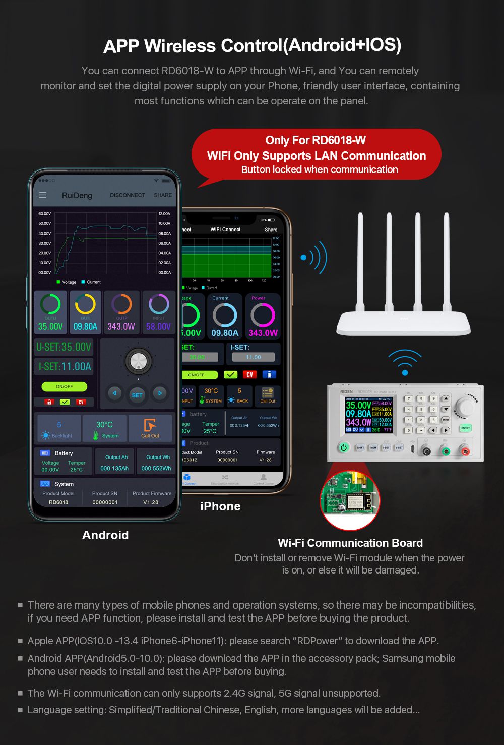
Android APP Instruction
2.1Mobile Phone APPInstallation
This App only supports Android 5.0 to Android 10.0 operating system, and there may be incompatibilities problems between APP and operating system, please install and test the software before buying the product. It will apply for location service, please agree and turn on the location service. After downloading the mobile APP zip-file, please install the APP in file manager.Don’t install or remove Wi-Fi module when the powered on, otherwise it will be damaged.This instruction is made for version 1.1.2, there will be little difference between different versions, and we do recommend you to download the latest APP for better experience.
2.1.1APPDownload
You can download the APP in Google Play by searching RDPower.
You can also download the RD60XX APP zip-file in this URL:
https://drive.google.com/drive/folders/1V0l6P1sIJilN1yBOsTO9YGLVdkuO0cX9?usp=sharing
2.2Installation Introduction
After the installation, you can see the icon as shown below:
RD6018 RD6018W 60V 18A USB WiFi DC DC adjustable Step Do
2.2.1APPUpdate
Click the APP icon, After the APP starts, it will automatically detect whether there is a new version, and it will remind you by popping the window. You need to check if there is a new version by manual detecting.
2.2.2APP Interface Display
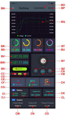
When finish the installation and succeed in connection, it will show the main page as shown in the right picture.
RD6018 RD6018W 60V 18A USB WiFi DC DC adjustable Step Do
BN: call out/ shut down sidebar
CB: set button
BO: connection button
CC: keypad lock indication
BP: export data to mobile phone folder
CD: protection status indication
BQ: data curve
CE: constant voltage/ constant current status
BR: actual output current
CF: screen brightness
BS: actual output voltage
CG: system temperature
BT: actual output power
CH: data group quick call out
BU: input voltage
CI: battery voltage
BV: preset voltage value
CJ: external sensor temperature detecting value
BW: preset current value
CK: accumulated output power
BX: ON/OFF button
CL: accumulated output capacity
BY: setting wheel
CM: model being connected
BZ: move the cursor to the left
CN: product SN number
CA: move the cursor to the right
CO: product firmware version
2.2.3APPOperation
2.2.3.1Network Distribution
RD6018 RD6018W 60V 18A USB WiFi DC DC adjustable Step Do
Picture 3
Picture 4
RD6018 RD6018W 60V 18A USB WiFi DC DC adjustable Step Do
Picture 5
Picture 6
RD6018 RD6018W 60V 18A USB WiFi DC DC adjustable Step Do
Picture 7
Picture 8
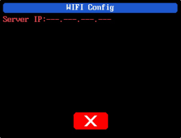
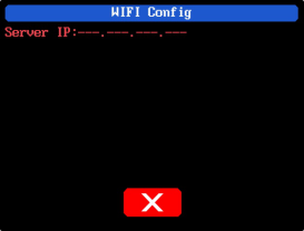
Connect Wi-Fi for the first time, please insert the WiFi board to the right place, then power on RD6012, you will see the blue LED blinks once. Set the communication interface to WIFI, restart RD6012, then place the RD6012 and the mobile phone close to the 2.4G router (the mobile phone must also be under the same 2.4G network, and the router must disable the AP isolation function and the WMM function).
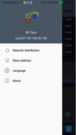
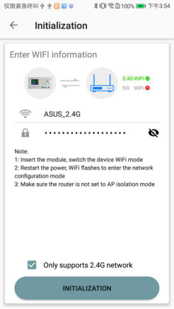
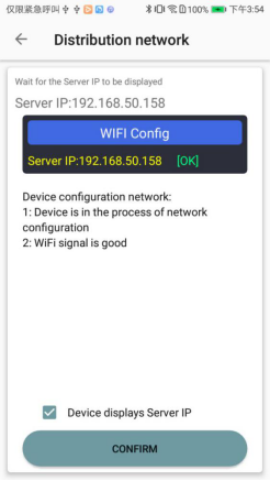
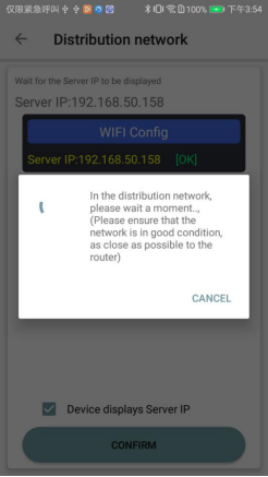
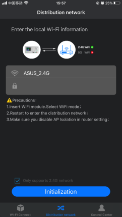
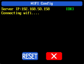
RD6012 will wait for the phone to connect as shown in Picture 3. Press“BN”to call out the sidebar, clicks on the“Network distribution”as shown in Picture 5, then enter the WiFi password and confirm you are using 2.4G network as shown in Picture 6. After 10 seconds, the RD6012 will obtain the IP address of the mobile phone as shown in Picture 4. Then click “Next”, fill in the WIFI password as shown in Picture 7, click "CONFIRM" below, wait for about 20s, it will show success as shown in Picture 8, then RD6012 will automatically restart, the distribution network is successful, return to the main interface and click“BO”(Connection). If the distribution network fails, please power off the module and re-operate in the same way (multiple networking failures you can watch the video and try to use the hotspot of the mobile phone to test).If you use Huawei brand phone, please turn off the random MAC address function.
3.2.3.2Proper Wi-Fi Connection
Android APP download and connection operation video:
https://youtu.be/QwyBEUCnp9c
When power on RD6012, it will connect Wi-Fi first, and then detect if it can be connected to APP, and it may not be connected successfully if the phone is under screen-lock status or the APP is running at the background. If the IP address of the phone has changed, you need to press the “left direction” button and then press “ENTER” button to reset the net, repeat 3.2.3.1 operation.
2.2.3.3 APP Operation
Android APP operation video:https://youtu.be/hqrF4keTfbE.
Click“BV”to set the output voltage, and use the wheel“BY”to adjust the value, the“BZ”,“CA”to change the position of cursor, click“CB”to set the parameter. Click“BP”to exports the voltage-current curve to excel file, up to 24 hours document can be recorded.
NOTE:
There are many kinds of Android phone, so the user interfaces maybe different on some brand phones or different scales of the same brand.
Application permission requirements, allow the necessary permissions when the APP is installed (allow background running, using Bluetooth, operation on the folder, reading the application list, etc.) and also set the permissions of the APP after installation: Allow background running, never shut down when lock screen, allow self-starting (it is used to prevent the system from forcibly exiting the APP when recording data), etc.
IOS APP Instruction
3.1Mobile Phone APPInstallation
3.1.1APPDownload
IOS APP can only supports IOS10.0-13.4 system, please search “RDPower” in the APP store to download, or search “RD6006” to find the APP,and there may be incompatibilities problems between APP and operating system.The software opened under IOS13 will apply for location service for the first time. Please agree and open the location in Settings-Privacy.Don’t install or remove Wi-Fi module when the power is on, or else it will be damaged. This instruction is made for version 1.0.1, there will be little difference between different versions, we do recommend you to download the latest App for better experience.
3.2Installation and Operation
IOS APP download and connection operation video :https://youtu.be/nH2HYwop0TE
You can see the APP icon (as shown on the right) when finished the installation.
RD6018 RD6018W 60V 18A USB WiFi DC DC adjustable Step Do
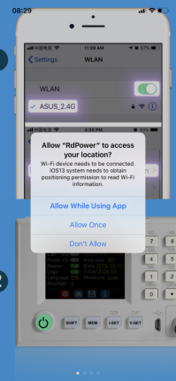
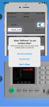
The first time you start the APP, there will be prompt as shown in Picture 10 if your mobile phone system is IOS13 or above, choose “Allow when using APP”, if your system is under IOS13, you can see the prompt as shown in Picture 11, please choose ”Wireless LAN and cellular mobile network”.
3.2.1APPUpdate
You can download the latest the software at APP store, this instruction is corresponding to IOS APP version 1.0.9.
3.2.2 UI Instruction
You can see the user interface as shown in Picture 9.
AN: connection button
BA: system temperature
AO: export data to mobile phone folder
BB: data group
AP: data curve
BC: screen brightness
AQ: actual output voltage
BD: battery voltage
AR: actual output current
BE: external sensor temperature detecting value
AS: actual output power
BF: accumulated output power
AT: preset voltage value
BG: accumulated output capacity
AU: preset current value
BH: model being connected
AV: output ON/OFF button
BI: product firmware version
AW: protection status indication
BJ: product SN number
AX: battery status indication
BK: main page
AY: constant voltage/ constant current status
BL: network distribution page
AZ: input voltage measurement value
BM: personal center
3.2.3 APP Operation
3.2.3.1Network Distribution
RD6018 RD6018W 60V 18A USB WiFi DC DC adjustable Step Do
Picture 9
Picture 10
RD6018 RD6018W 60V 18A USB WiFi DC DC adjustable Step Do
Picture 11
Picture 12
RD6018 RD6018W 60V 18A USB WiFi DC DC adjustable Step Do
Picture 13
Picture 14
Connect Wi-Fi for the first time, please insert the WiFi board to the right place, then power on RD6012, you will see the blue LED blinks once. Set the communication interface to WIFI, restart RD6012, then place the RD6012 and the mobile phone close to the 2.4G router (the mobile phone must also be under the same 2.4G network, and the router must disable the AP isolation function and the WMM function).
RD6012 will wait for the phone to connect as shown in Picture 13. Press“BL”to jump to the network distribution page and enter the password. Click “Initialization” and wait about 20 seconds, RD6012 will obtain the IP address of the mobile phone as shown in Picture 14. Then click “Configure Network”, wait about 30s, it will show success on the APP, then RD6012 will start normally, the distribution network is successful, return to the main interface and click“AN”(Connection). If the distribution network fails, please power off the module and re-operate in the same way (multiple networking failures you can watch the video and try to use the hotspot of the mobile phone to test).
3.2.3.2Proper Wi-Fi Connection
When power on RD6012, it will connect Wi-Fi first, and then detect if it can be connected to APP, and it may not be connected successfully if the phone is under screen-lock status or the APP is running at the background. If the IP address of the phone has changed, you need to press the “left direction” button and then press “ENTER” button to reset the net, repeat 2.2.3.1 operation.
3.2.3.3 APP Operation
IOS APP operation video:https://youtu.be/lXSw1CM9IY8.
Click“AT”/ ”AU” text label and enter the value to set the output voltage/ output current, then click at the blank area to return, if you enter a value exceeds the limit, it cannot be applied. Click“AO”to exports the voltage-current curve to excel file, up to 24 hours document can be recorded.
Click the personal center to set the software language or get help to use the APP.
PC Software Installation and Operation Instruction
Requirement: Win 7-Win10 system and the computer has Internet connection.
This PC software is designed by Hangzhou Ruideng technology CO., LTD, it has no virus, if your anti-virus software prompts for a virus warning, please allow all its features, otherwise it will affect the normal operation of the software. PC software supports Win7-Win10 system, and there may be incompatibilities problems, if you really need it, please install and test the software before buying the product. This instruction is made for version 1.0.0.8, there will be little difference between different versions, and we do recommend you to download the latest App for better experience.
RD6018 digital power supply file download link:
https://drive.google.com/drive/folders/1V0l6P1sIJilN1yBOsTO9YGLVdkuO0cX9?usp=sharing
4.1 Software Download
PC software download and basic operation video:
https://youtu.be/mjt1RMaah1Y
4.1.1 Unzip Files
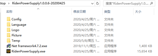
The first time you use this software, you need to install the driver program first, you need to click CH341SER to install the driver, the insert a Micro USB cable into RD6006/RD6012/RD6018 and wait for the computer to install the driver.
4.1.2 Unzip Files
Unzip the file to Disk(D) of the PC. You need to run Net framework4.7.2.exe to install the .Net environment, then click RidenPowerSupply.exe directly to use the software, please do not delete any files.
RD6018 RD6018W 60V 18A USB WiFi DC DC adjustable Step Do
4.2 Software Operation
4.2.1 Software Connection
Double clickRidenPowerSupply.exeto run the PC software.
WiFi connection is a test function, due to poor compatibility with some computers, if you cannot connect PC software via WiFi, please ignore this function. For this function, we do not provide any guarantee and technical support, and we will decide whether to keep this function based on customer feedback.
WiFi connection video link:https://youtu.be/ussQREniPuY
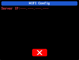
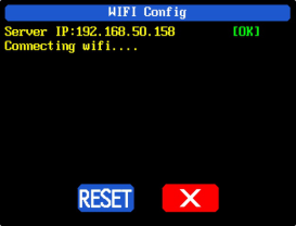
Click WiFi on the PC software and enter the WiFi name and password, set the communication interface to WIFI and reboot, you can see the display of RD6018 as shown in picture 15, and click “WiFi Network” to distribute network, wait RD6018 display as shown in picture 16(wait 1-5 seconds), click “NEXT”, wait for a while (about 20 seconds), the PC software shows connection successful, then click “Connect” to communicate.
USB connection: Set RD6018 communication interface to USB and connect RD6018 and PC, the PC software prompts the serial port has been updated and clicks online.
RD6018 RD6018W 60V 18A USB WiFi DC DC adjustable Step Do
Picture 15
Picture 16
4.2.2PC Software Operation Instruction
Choose the right communication port, baud rate, slave address (default 001), click“CONNECT”to start communication. If the communication succeeds, the power supply button will be locked automatically, the buttons will automatically unlock after 3 seconds of accidental disconnection, and the“CONNECT”turns to“DISCONNECT”; Click“ON”to turn on the output of the power supply, and it will turn to“OFF”.
4.3Functions Introduction
The PC software interface mainly has basic functions, firmware upgrade, Logo upgrade, version update detection and language setting...
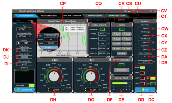
RD6018 RD6018W 60V 18A USB WiFi DC DC adjustable Step Do
CP: Voltage-Current Curve
DA: System Temperature(℃)
CQ: Battery information/
Data Group Quick Call Out
DB: System Temperature(℉)
CR: Calibration
DC: Constant Voltage/ Constant Current Status
CS: RD/DPS series switch
DD: Protection Status Indication
CT: Language
DE: Screen Brightness Setting
CU: Software Update
DF: Synchronize System Time
CV: About
DG: Output Current Preset value
CW: Input voltage
DH: Output Voltage Preset value
CX: Actual Output Voltage
DI: Firmware Version
CY: Actual Output Current
DJ: Serial Number
CZ: Actual Output Power
DK: Product Model
4.3.1 Basic Functions
PC software operation video:https://youtu.be/mjt1RMaah1Y
The basic functions of PC software: voltage/current preset, data group quick call out, calibration fine tuning, brightness setting, voltage and current curve exporting. You can rotate the wheel or enter the value to set the voltage and current, the graph above the button shows the real-time voltage and current curve. You can zoom in and out the curve by using the mouse wheel, double click the curve to auto adjusts the axis, you can right click on the curve to clean the curve or export the curve data to picture or excel.
4.3.2Calibration
The calibration fine-tuning function needs to be operated by a professional electronic person who has more than five and a half multimeter. It will change the system setting, incorrect operation may exceeds the hardware limit and cause damage, and the resulting damage is not covered by the warranty! The limit error of the product is generally much smaller than the nominal error, when the error is close to or even higher than the nominal error, you need to check if the measuring instrument is accurate.
RD6006 calibration operation video:https://youtu.be/c9sn1wY2mjE
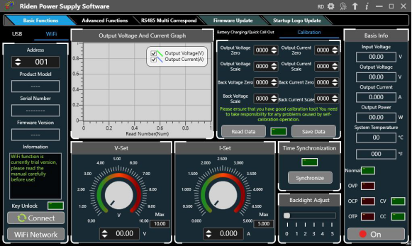
Click“Calibration”and enter the password “168168”, you can enter the Calibration Fine Tuning page(if you enter the password, by default you have accepted the above red letter agreement).It can read the calibration data after connection; click the arrow to fine tuning the data. According to the linear function y=kx+b, the constant b is equivalent to the zero value, the slope k is equivalent to the proportional value, adjust this two values so that the data will be close to the real test value.
Set the output voltage at 1V, adjust the output voltage zero point to make the multimeter display close to 1V, and then set the output voltage at 30V, adjust the output voltage proportional value to make the multimeter display close to 30V. In the same way you can set 0.1A and 3A output current to calibrate the zero point and proportional value of the output current.
Set the output voltage at 1V and calibrate the actual output voltage zero point to make the actual output voltage displayed on RD6012 close to the value on multimeter. You can set 30V and calibrate the proportional value of actual output voltage. In the same way you can set 0.1A and 3A to calibrate the zero point and proportional value of the actual output current.(This section does not provide technical support. If you do not understand, please check the related information).
RD6018 RD6018W 60V 18A USB WiFi DC DC adjustable Step Do
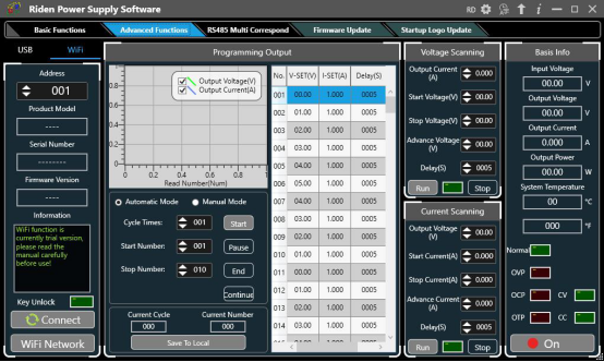
4.3.3Advanced Function
You can set the output voltage and current by chart in the advanced function page, you can set every step between 1 and 9999 seconds, you can set 200 steps max, it can output automatically or manually. You cannot choose other operation page when it performs programming output or other operations, you can only switch other page when it ends.
RD6018 RD6018W 60V 18A USB WiFi DC DC adjustable Step Do
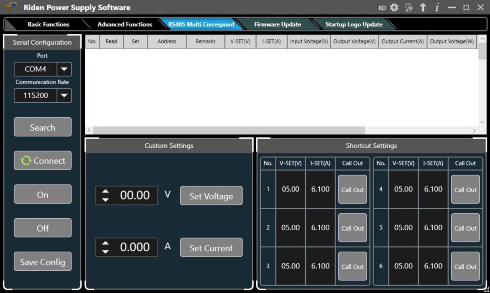
4.3.4RS485 Multiple Devices Communication
RD6018 RD6018W 60V 18A USB WiFi DC DC adjustable Step Do
4.3.5 Firmware Update
Firmware update operation video:https://youtu.be/NOoLfDw0DiY
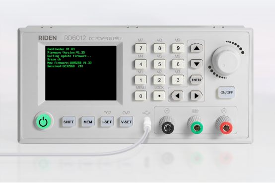
Press and hold “ENTER” and power on RD6018, enter the boot mode, then connect it to computer, there will be “boot mode” in the mode information text box, then click“Firmware Update”, a firmware update prompt will pop up on the interface, and click “Now” to upgrade. (You can update the firmware under the normal mode, if it cannot be started up normally, you should press and hold the“ENTER”button and power on, update it under boot mode. It doesn’t support firmware update under WiFi connection mode).
During the firmware upgrade process, the interface is displayed as follows:
RD6018 RD6018W 60V 18A USB WiFi DC DC adjustable Step Do
4.3.6Boot Logo Update
Boot logo setting video:https://youtu.be/vuVhBsohWts
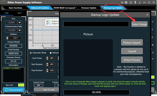
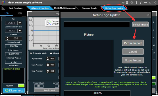
Click“StartLogoUpdate”, a Logo upgrade prompt will pop up on the page, please select a picture with a size of 320x240 and a resolution of 96dpi. Some logo samples can be used in the installation package.
RD6018 RD6018W 60V 18A USB WiFi DC DC adjustable Step Do
Click “Picture Import” and RD6018 will reboot automatically.
RD6018 RD6018W 60V 18A USB WiFi DC DC adjustable Step Do
4.3.7Version Update Detection
Click“Software Update”,the software will automatically detect if there is a new version, if so, an update prompt will pop up on the interface.
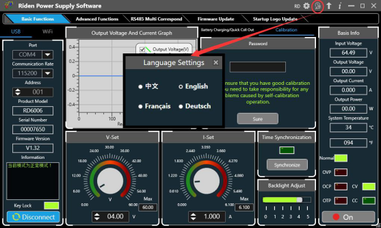
4.3.8Language Setting
Click“Language”, a language setting prompt will pop up on the interface, you can choose Simplified Chinese, English, France and German.
RD6018 RD6018W 60V 18A USB WiFi DC DC adjustable Step Do
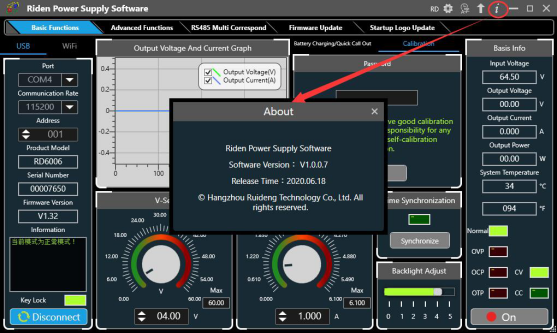
4.3.9 About
Click“About”, you can check the version number, publish time and copyright Information.RD6018 RD6018W 60V 18A USB WiFi DC DC adjustable Step Do
Affected by the injection molding process, there are slight traces at the button holes of the shell. It can hardly be found in normal use. It can be found under the light (the shell is not crafts, don't be overly picky). as shown in picture 1,if you care, please don't buy this product

Go to Buy: RD6018 RD6018W 60V 18A USB WiFi DC DC adjustable Step Down voltage bench Power Supply Buck converter & 800W1000W AC DC PSU
LONSDOR Key Programmer Porsche Piwis III GM Tech2 USB Link 2 CAN Clip wiTech MicroPod 2 T300 key programmer locksmith tools a b c d e f g h i j k l m n o p q r s t u v w x y z
Share to Pinterest